CINDERCLOCK
This is a demonstration of our work process, written as the design rationale for our first product. Every decision below is here with the reasoning that produced it. If you are deciding whether to hand us a hardware project, this document is the evidence.
Firmware and documentation are on GitHub.
For what the device does rather than how it was decided, see the product page.
CinderClock launches on Kickstarter on 1 October 2026.
The device this document describes is finished. The pre-launch page is live now, and Kickstarter will tell you when the campaign opens.
GET NOTIFIED ON KICKSTARTER →


CinderClock: Kickstarter overviewwatch on YouTube ↗
What is this?
CinderClock, our debut product, is a multi-purpose standalone desktop clock. It is built to keep your phone away from the delicate matters of sleep and focus.

CinderClock launches soon. Subscribe to be among the first ones to know.
Backers on the list get the launch price.
This list is only for CinderClock.
Why?
After many failures of the iPhone alarm (Attention Aware features), we asked why we use our phones to wake us up in the first place.
Back in the day we used phones for the convenience. As our devices got more and more loaded with unnecessary things, the convenience was replaced by burdens:
- Information overload, with notifications accumulated over the night.
- Fiddling with touch controls when you are half asleep.
- Blue light from millions of flickering pixels hitting your eyes after eight hours of darkness.
In search of a dedicated bedside alarm clock, we found that nothing on the market was worth its money. The cheap end is crowded with trash. The expensive end devices want an app, an account, or a subscription: the Philips SmartSleep lists at $199.99 and the Loftie at $169.99, with Hatch charging $49.99 a year for its content library and Loftie $59.99 for its own. The full spectrum, from landfill ambassadors to gimmick stands, did not have a single member worth the cost with the features we wanted.
So for our first product launch we set out to make our own alarm clock.
Our goal was a standalone device that kept time, played audio, and was programmable. Programmable here means it stores user-created alarm programs and follows them automatically. Most alarm clocks, your phone app included, have very simple programming options. You can set one alarm for a specific time, and have it repeat on certain days. That's it. We feel that this is too limiting.
What if you want it to ring only on certain days of the month? Ring 2 days on and 2 days off regardless of the week? Follow your local sunrise and sunset times so you wake up with the sun? Ring for 3 weeks in a row with one week off, if you work shifts?
These are not gimmicks either. Sun following was the feature we wanted for ourselves most. Having an app do that on the phone defeats the first part of the brief. The rest are useful to the many people who don't follow a 9 to 5.
With this in mind we got to work.
The beginnings. Tap any image to enlarge.
Intentions, Constraints, Systems
Whenever we do anything, we always start with core principles. At Endothermal Systems the core principles are Intentions, Constraints, and Systems. Good intentions set you on the right path, good constraints focus your attention, and good systems get you to the destination.
The Intentions with this project were:
- to take control of your sleep back from your phone
- to make the hardware conform to your sleep needs, not the other way around
The Constraints were:
- the device must be standalone, with no reliance on external entities
- mechanical interface
- modular design
A System is a network of methods you can run again and again. The core method we use is of the ideal outcome. Visualize an ideal outcome of whatever you hope to achieve, adhering to the rules of reality. If it satisfies you in that ideal form, then workout the details of how to get there. If, however, the solution you propose cannot satisfy you even in its ideal form, then scrap that idea altogether.
"A wise man starts with the end, the fool ends with a beginning".
The method of ideal outcome requires you to consider every possible solution you can think of. In theory that is. List out all possible solutions to this problem, evaluate each one according to a defined scale, visualize the ideal outcome of each one, reevaluate, keep the ones that pass, scrap the rest.
If you cannot do this due to limited information, go one level below, break the problem into smaller problems. Try to define ideal solutions to those and find practical candidates for the them. Do this until you reach the smallest atomic problem and go back up to the top level problems. This process is commonly known as analysis.
There are more nuanced ways to our System which will become apparent as you read on.


Part one: Requirements
Once the top level constraints are set it is time to define the lower level requirements.
Standalone. The device must be standalone, with no reliance on external entities. Which means:
- connection to the internet must not be needed for it to work
- it must operate on battery power for a prolonged time, 2 weeks or more
- it must be portable, to easily take it to different rooms/apartments
Mechanical interface.
- every input must be mechanical, with clear tactile feedback
- each input device must be the best fit for its purpose
Modular design.
- every significant component of the device must be a repairable and replaceable module. This includes the screen, the electronics modules, the enclosure, and the input devices.
- software must accommodate the modular design. There must be appropriate handling in place for when one of the components is missing/replaced.
Part two: Components
At the basic level an alarm clock has three components: a display, a computer, and a speaker.
The display
A display can be analog or digital. An analog watch face is of little use on a programmable device, since there is no useful way to show program options on a pair of hands. So the device must have a digital interface, and the question becomes which kind.
The screen is the part you interact with the most, so it was chosen first. It has to be bright enough to read across a room and dim enough to not wake you up unintentionally. It has to be low power, because the device runs on a battery. It has to be low fidelity to save power and avoid too much light hitting your eyes in the morning. And it has to be able to carry a menu to display all program options.
Seven technologies could do some of that.
| Option | Can show menus | Power | Cost | The failing |
|---|---|---|---|---|
| 7-segment, 4 digit | No | Low | Low | Commercial parts stop near 14 mm digits and show nothing but digits |
| Chained 7-segment modules | Barely | Medium | Medium | Many modules wired by hand, and the face degrades as the count grows |
| Character LCD (1602 / 2402) | Limited | Backlight always on | Low | Low contrast despite the backlight |
| VFD | Yes | High | Medium | Thermally inefficient, closer to an incandescent lamp, so it drains a battery |
| 7-segment plus small OLED | Yes | Low | Medium | Two screens split the face and the gains cancel |
| Monochrome OLED | Yes | Low | Low | Pixel burn-in under uneven use |
| MicroLED | Yes | Low | Prohibitive | Fabrication complexity prices it for AR headsets and luxury televisions |
If you could combine independent pixel control, LCD wear resistance, VFD brightness, and low power at low cost, you would have made the best screen ever. In the real world every option fails somewhere, so the job is to choose the failure you can handle.
Pixel burn-in is the only failure in that table that software can address, therefore the OLED screen was chosen. To manage the burn-in every pixel must be evenly lit. If you use one picture at the same place all the time then that region of pixels will burn-in much faster and it will look off compared to the rest of the screen. To manage this issue all you have to do is to make sure that each pixel on the screen is lit for the same time interval, cumulatively. The ideal version of this is to show your image for one time interval and then invert the whole screen for another time interval. But there is more to it than just this, which we will discuss in the software section.
Finding the part took longer than choosing the technology. We wanted something like the panel on a Bambu Lab P1S printer, large enough to read and detailed enough for menus, and it is not a thing you can search for directly, because you do not know the terms it is sold under in many cases. Reverse image search and some advanced Google-fu techniques later we found it but it was too expensive and very hard to source, only one company had a listing for it on Alibaba.
A 3.12 inch 256px by 64px SSD1322 panel eventually surfaced through a chain of related listings on Aliexpress. The 64 pixels of height carry either a large time font or a full menu. The 256 pixels of width carry the time, the date, and the alarm panel at once.
The computer
Computer here does not refer to a PC or a specific chip. It is the general term for a processor that performs computations. The computing part of the clock has two jobs: timekeeping and programmability.
Timekeeping on a digital device wants a crystal oscillator based chip called a real time clock (RTC). The most commonly available one is the DS3231 module. It is reliable, temperature compensated, keeps time offline from its own coin cell, and it works over I2C (a simple communication protocol).
It is designed around a rechargeable coin cell and trickle charges whatever you fit. Put an ordinary non-rechargeable cell in it and the cell will be damaged. The fix is to remove the small resistor connecting the power rail to the battery, which disables the charging circuit, after which a standard cell is fine to use. This chip could have been integrated into the PCB, but it would be against the modularity principle.
For programmability on a relatively simple device you can go with a microprocessor or a microcontroller. Both are computers. Microprocessors are faster but need peripherals around them for memory and input/output. Microcontrollers are complete computing units but are less powerful. For low power embedded systems, microcontrollers are the better fit.
One of the most available and best documented microcontrollers right now is the ESP32. Its ease of use and low cost make it a good board for this application, especially given the modularity constraint. It is not the first choice for commercial products, where companies drive cost down to pennies, but the versatility of an ESP32 at a few dollars more than a penny chip is justified here, even more so when we use most of its capabilities.
We chose the ESP32-S3, the more capable model of the S variants. In line with modularity we use a dev board version of the microcontroller, seated on pin headers on our custom PCB rather than soldered to it, and the same treatment goes to every other module on the board.
The speaker
Choosing the right speaker matters for an alarm clock. The sound must be clear and loud, and the part must be easy to source.
The ESP32-S3 has no digital to analog converter and no audio amplifier of any kind. It has an I2S interface, which is a digital audio bus, so an external amplifier is the only path. The common part for the job is the MAX98357A, an I2S class D amplifier that is cheap, widely available, and well documented, and which comes on open hardware breakout boards from several vendors.
It drives 4 ohm and 8 ohm speakers, and we chose 4 ohms for volume. From a 5 volt supply it delivers 3.2 watts at 4 ohms against 1.4 watts at 8 ohms. The lower impedance draws more current, and that extra current is where the loudness comes from. On a device that runs from a battery this is a deliberate trade: the amplifier only draws that current while an alarm is actually ringing, which is a rounding error, in theory, against the standby current that sets the runtime.
Among the 4 ohm speakers on the market we found a particular 30 mm by 30 mm unit to be the best. It has clear sound, a small form factor, and an acceptable retail price of about 3 dollars. It has no official name. Many AliExpress vendors carry it in their stores simply as a "30x30 mm speaker".
With these components a proof of concept was put together on a breadboard.


The rest of the board
Screen, computer, and speaker make the skeleton. A consumer product needs a bit more.
An SD card module, the Adafruit 4682, holds a card with push to eject access. This lets us store a large number of audio files and lets users upload their own. A bare SMD socket would have worked, but it would have needed additional small capacitors and an SMD assembly step, which we wanted to avoid. Plus modularity constraint. A board like this should be fully through hole for maximum hobby repairability.
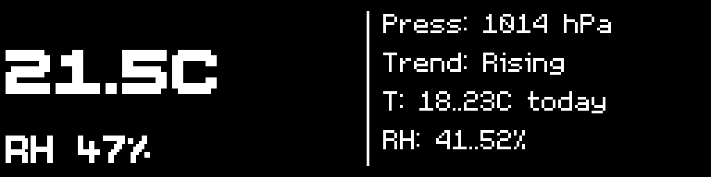
Environmental sensing was an easy addition, since the only thing on the I2C bus so far was the clock. A BME280 gives temperature, humidity, and pressure. This is what we mean by using the whole chip. Modules like that raise the value of the device at marginal monetary cost and near zero development cost.
A light sensor lets the device adapt its brightness to the room. A BH1750 module handles that, over I2C.
The board also breaks out its live buses on labelled expansion headers: I2C twice, SPI, UART, and the I2S audio bus. The audio header is the interesting one, because it means the amplifier can be swapped for a different one with no board revision at all. A modularity claim is worth what its connectors are worth.
A note on sourcing. We prefer the most common, best documented part available, because sourcing availability and reliable documentation are what make a product repairable and long lived. Twice in this project the common part did not exist. The display had to be hunted through unrelated listings, and later the charger did too. When no common part satisfies the constraint, the constraint wins and we go hunting.


Part three: Interface
Setting a time takes two motions. You move between fields, and you change the value under the cursor. That single observation removed direct digit entry before any comparison started.
| Control | Two motions | Fast scrolling | Pins | Failure |
|---|---|---|---|---|
| Four buttons | Yes | By auto-repeat | Four | Fixed scroll rate |
| Clickable dial | Yes | Yes | Three | One axis, so field movement and value changes share a motion |
| D-pad | Yes | By auto-repeat | Four or five | Same behaviour as four buttons at the same or higher pin count |
| Analog joystick | Yes | By holding a direction | Three | Analog axes cannot wake the processor from sleep |
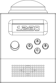
To interact with the device we chose only mechanical inputs: one analog joystick, four tactile buttons, and one large arcade button. The joystick gives motion in four directions with variable intensity, closer to the center or further from it, plus a tactile switch in its stem, five inputs from one component on three pins (X, Y, Switch; V+ and GND do not count as they are not going into the MCU).
The joystick moves between fields horizontally and changes field values vertically. Intensity is tied to speed, so holding it at the extreme of its travel increases a value faster than holding it part way in the same direction.
The four buttons give dedicated controls for specific, reusable actions:
A, Action. Dismiss alarms, start and stop timers, and the action button in games.
B, Back. The universal back button, which reverts changes on any screen.
C, Confirm. Confirms a selection and acts as the primary save button, and doubles as a secondary multipurpose button for showing and hiding extra items, such as centiseconds on the stopwatch.
D, Menu. Primary multi-purpose button. Opens the main menu from standby and returns to it from sub-screens. While an alarm is ringing it is the snooze button. On the Display Test screen it toggles inversion, so a panel can be calibrated against both polarities.
Two dedicated buttons and two multipurpose buttons offer great versatility without imposing limits.
The 100 mm arcade button is tied to the Action button and performs the same functions. The two serve different situations. The small Action button is for operations inside the clock interface. The arcade button is for dismissing an alarm early in the morning without aim, and for flapping the bird in the Fly Bird game.
The result is a complete control interface that anyone familiar with gaming consoles knows how to use.


The four keys sit on a separate riser board, not on the main PCB. The control layout can be changed without touching the main board. For example, the button order can be remapped or repositioned. Two risers were made: one with tactile switches, and the other with hot swap mechanical key sockets.

Part four: Audio
Audio took the longest of anything in the project. It is where the difference between assembling parts and engineering a system really shows.
The first attempt was the obvious one. Add the standard ESP32-audioI2S library, which drives the MAX98357A over I2S, and move on. It added 500 kb of library to decode MP3 files, and it carried its own real time operating system inside it, which fought the one we were already running.
Which raises the question of why a clock needs an operating system at all.
A microcontroller runs one loop. Draw the screen, read the joystick, check the alarm list, and polls the sensors. A full redraw of a 256px by 64px OLED over SPI takes tens of milliseconds. Audio does not tolerate that. The amplifier consumes 44,100 samples every second at a fixed rate, and if nothing refills its buffer during a redraw it runs dry and you hear it. So audio cannot share a loop with the interface. It has to be a separate job the chip switches to on its own schedule, which is what FreeRTOS is for, and the ESP32-S3 has two cores, so it does not even have to take turns. Audio gets one core, the interface gets the other. Once you own the scheduler, a library that also wants to own it is a problem.
Switching to the older I2S driver clashed with the new ADC drivers, so the ADC went legacy too, which produced its own downstream errors and semaphore conflicts that crashed the system on boot.
An external MP3 player module, the DFPlayer, was the next attempt. It works, and it has its own decoder chip. But it has a long mounting time, so every sound means connecting to it and waiting while it searches the card. That is unusable for interface clicks. You also cannot browse the card from the device, so you have to already know the exact path of the file you want. Scrapped. The ideal solution method would have rejected it before trial, but we needed to fiddle with it for another principle: Discovery. Sometimes wandering about can bring unexpectedly useful inspiration.
The third approach was to go back to the basics. A WAV file is a 44 byte header followed by samples. The header states the sample rate, the bit depth, and the channel count. There is nothing to decode. Once the header is read you are copying bytes from a card to a peripheral, and the peripheral sets the pace. This would lose the MP3 capability and require only WAV, which is a manageable issue.
So the audio is one FreeRTOS task pinned to its own core, doing nothing else. It waits on a queue one item deep, written so a new command overwrites a waiting one instead of stacking behind it. Three commands reach it: play a file, play a tone, stop. On a play command it opens the file, reads the header, and loops: take the SD mutex, read 8 kb, release the mutex, apply volume as an integer multiply, duplicate each mono sample into left and right, hand the block to the I2S driver.
That last call blocks until the DMA has room for it, and that is the entire timing mechanism. The hardware throttles the task at exactly the audio rate, so the task never has to guess how fast to run. The mutex is held only around the card read and never across the write, because the write can block for 93 ms.
The I2S channel opens once at boot and closes only for light sleep. The driver is configured to push silence into empty buffers and not leave them stale. Closing the channel between sounds makes the amplifier drop its clock, and it takes 50 to 200 ms to lock again, which is longer than a button click, so the click would never be heard at all if we unmounted during operation. This produces a tiny issue of the first sound effect (clicking a button) not play when you wake the device from light sleep. Again, a manageable price for a greater cause (power optimization).
Mono files play through a stereo channel on purpose, because the S3's I2S driver has a bug in mono slot mode where it emits alternating zero samples.
Part five: Programs
Programs are the core feature of CinderClock. We listed out the possible programs in the beginning, all of them can be broken down to fundamentals.
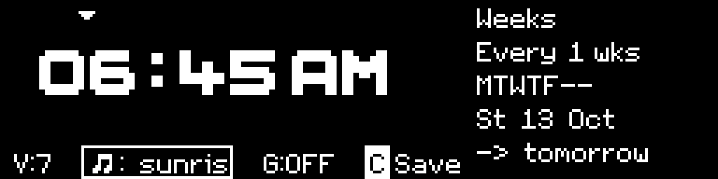
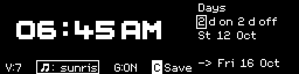
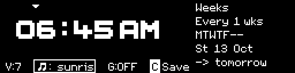
The recurrence model rests on one setting called Cycle, which takes the value Weeks or Days and changes the meaning of every row underneath it. In Cycle of Weeks an alarm fires on the weekdays you tick, every Nth week, which expresses "weekdays at 7:00" and "every other Tuesday" with the same two controls. In Cycle of Days it fires every N days counted from a start date and ignores the day of the week entirely, which expresses "every 3 days". When Cycle is set to Days, the day of week row disappears.
The alarm list writes patterns back in plain language, as Daily, Weekdays, Every 3 days, 4d on/2d off, so the list is readable at a glance. And each editor shows a live next-ring line computed by the same code the scheduler uses to decide whether to fire, so the preview and the behaviour cannot disagree.
What follows is everything the device does.
Alarms. Five types: one-time, repeating, On/Off duty cycle, sunrise, and sunset. A repeating alarm takes any pattern the calendar allows: every day, every 2 days, every 14 days, weekdays, weekends, chosen days. An on/off alarm adds a duty cycle, so "3 days on, 2 days off". Each alarm carries its own sound file and its own volume, under a master volume that caps all of them. A pre-alarm can give a gentler cue some minutes ahead with its own sound. An alarm rings for 5 minutes and then logs itself as missed. History keeps the last ten events with their outcome: DONE, MISSED, SNOOZED, NO-RING (device was off). You dont't have to doubt yourself or the device.
Alarms are never silent. If the card is missing or the file is unreadable, a built-in siren plays, and muting the interface sounds does not mute alarms. There is no mute path for alarms at all.
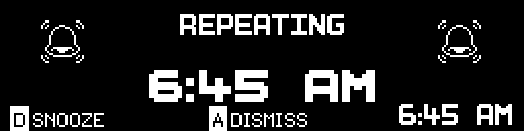
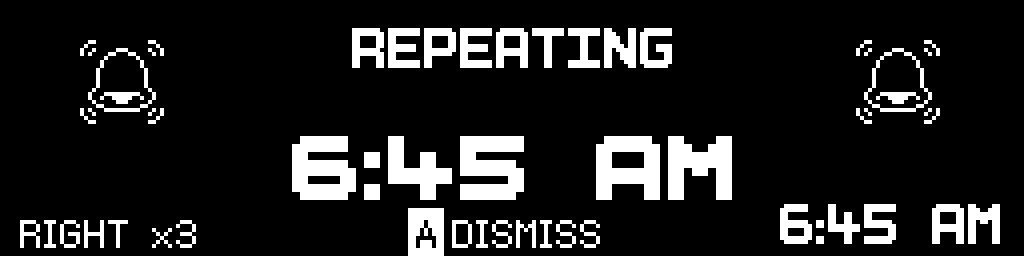
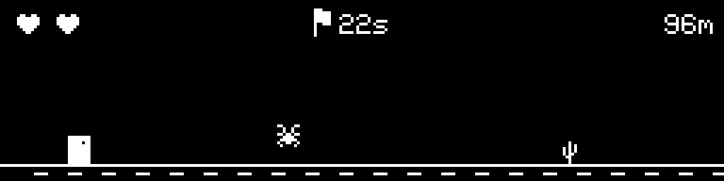
Getting it to stop. Dismissal is the 100 mm arcade button, sized to be hit without aiming. Snooze is deliberately harder and offers three modes: a single press, three presses at least half a second apart, or a sequence of randomly drawn joystick directions that each have to be fully released before the next one counts. The random sequence asks for 10 to 30 moves, new sequence every time. Snooze is capped at three per alarm. An alarm can also be gated behind a game, win the game to dismiss, lose and try again in 5 min (snooze); a third loss dismisses it automatically (you are probably awake at that point).

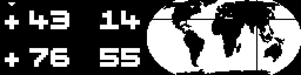
Sun follow. Sunrise and sunset are computed on the device from latitude and longitude entered in degrees and minutes, with the UTC offset derived from longitude and editable. A world map with a crosshair sets a position by eye, so coordinates do not have to be known exactly. Times recompute daily. Nothing in this touches a network.
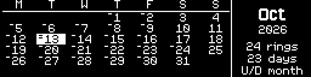
Calendar. A month grid with short ticks beside each day number, one tick per alarm, stacked up to four, with monthly totals. The ticks are drawn from the scheduler code, so the calendar doubles as a check on a recurrence setting. An alarm set to every 3 days should march across the month in threes.
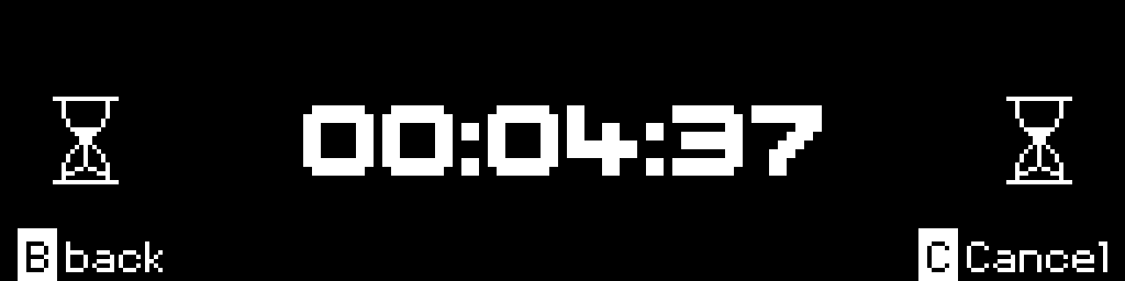
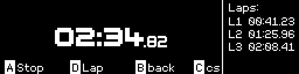
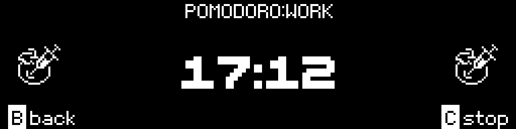
Timers and stopwatch. Saved, editable timers with presets, running in the background while you go do something else in the menus. A Pomodoro cycle takes work and rest periods from 1 to 999 minutes and announces each phase change with a countdown and different jingles for work and rest. A stopwatch with four laps and centiseconds, which can be hidden, because a fast changing display is a distraction on a desk. One joystick move from standby opens a quick menu for alarm, timer, and stopwatch.

Ambient. A sound loop with a slow full screen animation, for sleep or focus: Fire, Rain, Blobs, Life (Conway's game of life), and Waves, at about 10 frames per second. Reactive mode drives the animation from the audio, so a sudden sound seeds a spark in the fire or a glider in Life. Pendulum mode ticks on alternate seconds, locked to the second the clock is displaying, with the sound built into the firmware so it needs no card. Sessions run from 5 min to 6 hours, or endlessly, with optional fade-out and auto-dim.


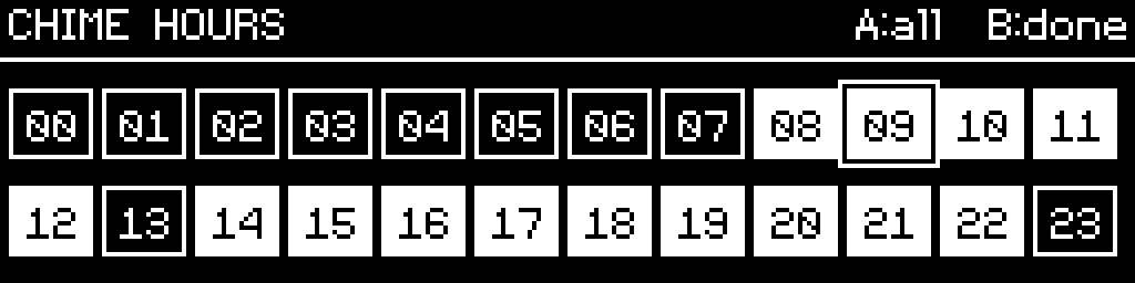
Chime. An hourly strike with five modes: off, every hour, a daytime window, sunrise to sunset from your coordinates, or specific chosen hours. It ships set to 08:00 to 22:00, but OFF. It strikes by count or once, and it always yields. During an alarm, a snooze, a game, or a firmware update it will not start, and if it is already striking it stops.
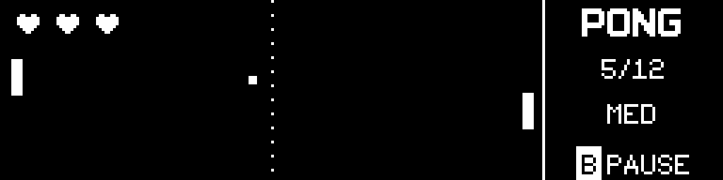
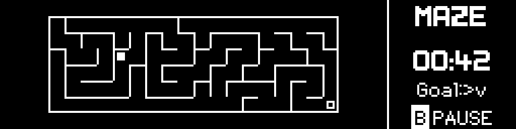
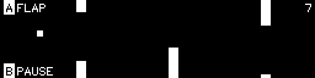
Games. Eight, at three difficulties each: Ping Pong, Maze, Fly Bird, Space Dudes, Frank, Bricked Out, Wild Runner, and Meltdown. High scores are kept per game and per difficulty.
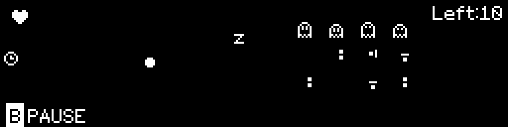
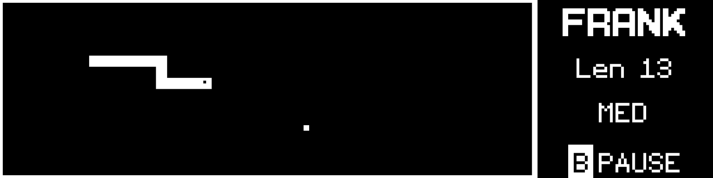
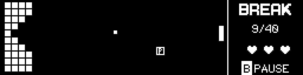
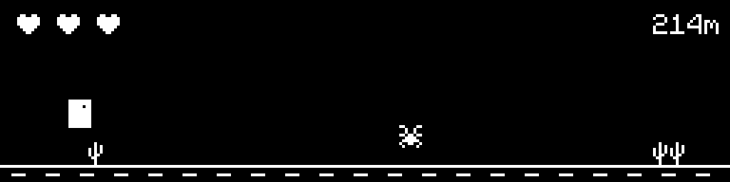
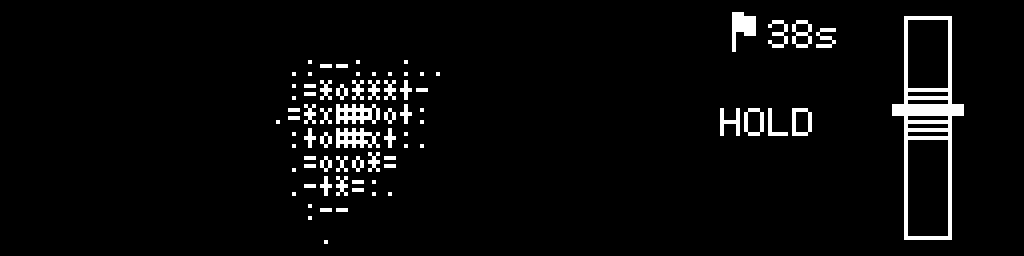
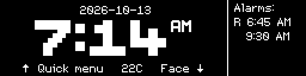
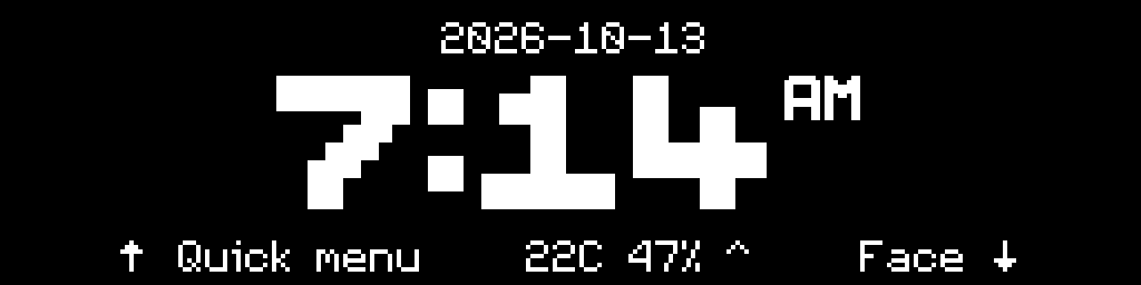
The watchface. Two standby faces, 12 or 24 hour, seconds and date optional. Six brightness levels, plus automatic dimming from the light sensor and a night level below the manual minimum. Two font themes. Four screen savers, Checker, Distribute, Jump, and Thermal, which are the burn-in management to even out pixel wear.
More details for the burn-in management as we discussed. The initial attempt was to simply invert the whole screen, white to black and black to white, but it looked off and way too bright. The issue was that the driver sets a limit on the current per row of the screen; a highly loaded row needs more current but can't get it so each pixel dims a little to compensate. This makes that row noticeably dimmer than the rest. Instead of full screen inversion we use half screen, checkered pattern inversion. Which goes in 3 cycles: white on black (the default), checkered inversion (odd pixels), checkered inversion (even pixels). This way each pixel gets its time and all of them are used the same. But, the checkered pattern creates jagged edges on the images. To avoid this we added a solid outline. This adds a bit more time for those outline pixels, a reluctant trade-off here. A better solution might be developed later.
The Distribute screensaver adds spacing between each digit so those do not use the same pixels. And the Jump moves the time string left to right to use those pixels more. Both of them are not ideal, but they are useful for people who want to avoid inversion at all.
There is one watchface that is just the smallest font which lits up only about 100 pixels, for absolutely minimal setup. And another face which is just the outline of the time string, lits up a fraction of the pixels compared to the default.
Thermal is just an animation.
So there is something for everyone.
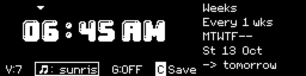
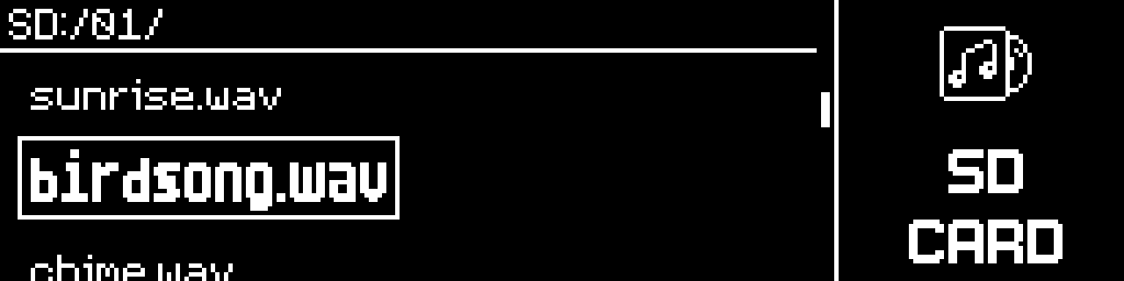
Files. Alarm sounds are WAV files on a removable card: PCM, 16-bit, mono, 44100 Hz. To get them onto the card without removing it, the clock raises its own WiFi hotspot with a file portal on it. The WiFi is off at boot, you turn it on by hand, and it closes itself after 5 minutes of idling.
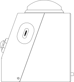
Updates. The case has no external USB port. We fitted one early on and it spoiled the face. And for the most people it is not needed at all. Firmware arrives two ways instead. The default is a file dropped into that same audio portal, which needs no internet, no server, and no account. The other is the clock joining your home WiFi to fetch a release from us over TLS. That path is optional, and the clock never checks for updates on its own.
Both paths flash the same way. The image carries a checksum verified before a single byte of flash is written. It installs to a second partition, and the bootloader reverts to the old one unless the new one reaches its main loop and survives for 60 seconds. Alarms, settings, history, and saved timers are not touched. The self test deliberately checks nothing else: not the SD card, and not the clock chip. Losing power at any point leaves you on the previous firmware.
Documentation. A 28 section manual on the clock's own screen, and the full manual served from the firmware over that hotspot, with no card and no internet needed. The device explains itself without this document.
Part six: Enclosure
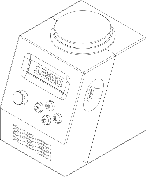
Connecting the arcade button to the board and sizing it up settled the scale question immediately. In our heads the device was about two cans of coke. In fact it is about the size of a toaster. That is fine. It is still portable, and the extra bulk helps with the tactility.
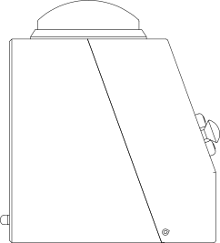
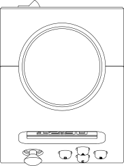
The finished enclosure measures 140 by 160 by 170 mm, printed in PLA, PETG is also an option. The front face is not flat: the bottom speaker section is vertical, and the interface panel is raked back 70 degrees for the best viewing angle from a bedside table. Upright, you cannot see the screen properly.
That angle then decided how the box is made.
The interface plate carries the holes for the screen and the controls, so it cannot sit at an angle to the build plate, or layer lines run diagonally across the whole visible face. It has to be printed parallel to the plate. Printed as one piece the box also needs a great deal of support built on top of internal faces, removing them is hard and ruins the face. The first single piece print took 26 hours at 0.2 mm layer height and came out with a set of serious issues that added up to an unusable prototype. Reprinting with different settings fixed some of them but not enough.
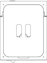
So the box is cut along the same 70 degree plane that set the geometry, into front and back halves. The two pieces join with a sliding dovetail, a stopper piece at the top makes sliding go only one way, and a pair of M2 stopper screws at the bottom prevent unsliding. Small test pairs of just the joint were printed to dial the fit, and it took three tries to nail it.


The back panel now prints with almost no support. The front panel uses grid support for easy removal, with top interface layers raised to 6 and a two layer top Z distance, 0.32 mm at 0.16 mm layer height. If you have AMS you can simply use PETG support interface when printing with PLA. These settings use more filament, but the support comes off in one piece, which matters a lot more.
The same geometry through the slicer, before and after the cut.
And the same prints on the machine.
Even with manufacturing methods in mind during the design the reality collides with your expectations. Fast iteration is key.
Part seven: Power
Two choices mattered here: the cell and the charger.
We wanted 18650 cells, because a standard 18650 is easy to buy anywhere and the lipo market is a thousand unreliable variants. And we did not want to weld them into a pack because that goes against the repairability. Modules exist for exactly this reason. The cells drop into holders and the leads connect to the circuit, so any cell can be removed and replaced at any time with no welding. The holders add a little resistance, which is negligible at these currents.
The charger was the harder half. The usual charging modules are notorious in the hardware community, and a battery board has to account for over-current, over-voltage, over-temperature, and short circuit protection, plus charge and discharge limits. Nothing on AliExpress carried all of it. The part came from Taobao instead: one board with the full protection set, plus separate leads for battery input and current output, which many boards do not break out at all.
This is the second of the two sourcing cases mentioned earlier. Both times the constraint was safety or capability, and both times the common part did not fit the bill.
Field notes
Some decisions were wrong. That is the nature of the process. The System turns the failures into rules.
Troubleshooting. Audio stuttered early on, so a software ring buffer went in between the card reads and the DMA to smooth the stream, generously sized. It got worse in a specific way: the stutter became rhythmic, roughly three times a second, which is the ring buffer oscillating between its own high and low watermarks at the rate the audio drains it. Deleting the buffer fixed it. The DMA ring already underneath holds 32 descriptors of 512 frames, 64 kb, which is 371 ms of audio, against a card read of about 40 ms. The headroom being added already existed, in hardware, nearly ten times over. The issue was with the shared SPI bus between the SD card and the OLED screen. The rule: try to identify an easier culprit.
Adding more load on the software to fix something in the hardware setup is not always desirable.
Reasons behind choice. The processor was chosen as an ESP32-S3 N16R8, with 8 mb of PSRAM, on the expectation that smooth audio would need large buffers there. It does, only if you use a library, which we dropped in the process. A DMA copy path through the PSRAM cache creates coherency problems that are not worth the space, so the working path uses 16 kb of internal SRAM and a 64 kb DMA ring, and the firmware runs on the lesser part as well. The reason we picked the part turned out to be wrong. The part survived on other grounds, at $5 with headroom for everything else the device does. The rule: document the reasons for the choices, so you find out when they no longer true.
A related result sits next to it: doubling the DMA ring to 128 kb works, and then fails after about three minutes, when the channel is torn down for light sleep and cannot be reopened because the heap has fragmented and there is no longer 128 kb of contiguous DMA-capable memory. 64 kb reallocates every time. The answer to a fragmentation problem was to ask for less.
Better tomorrow. The OLED header on the PCB was placed mirrored on the first board. The orientation had been reasoned through repeatedly, in the software and against the physical module, flipping the board mentally and by hand, and it still ended up wrong. The rule: recheck with a fresh mind.
Taste matters. One decision was reversed on taste. A full icon set was designed and inserted into every menu, then removed because it did not fit the rest of the interface. Judgement about how a thing looks and feels is an important part of the engineering work, and what a client is paying for.
The icons that looked great on the image looked terrible when applied to their purpose. The big icons clashed violently with the menu item highlights, so they were moved to be menu titles instead. A smaller icon set was used for the menu highlights. The rule: always try it on.
Endothermal Systems does not just do engineering as a separate part of product development. We deeply integrate into the whole process. We view different perspectives and wear different hats made for each problem.


The build in detail
Tap any image to enlarge.
Limitations
- Battery runtime has not been measured. The 2 week requirement stands as a design target. Optimizations and testing are underway.
- The device does not light a room. Philips and Hatch put a real sunrise into a dark room. A lamp extension module is possible and the PCB has the port for it.
- Sunrise and sunset accuracy degrades above roughly 65 degrees of latitude, where the sun may not rise or set on a given day.
- WAV audio files only. MP3s and other formats cannot be used.
- History holds ten entries, the stopwatch holds four laps, and two Pomodoro presets are stored.
- No claim is made about sleep quality.
What is open
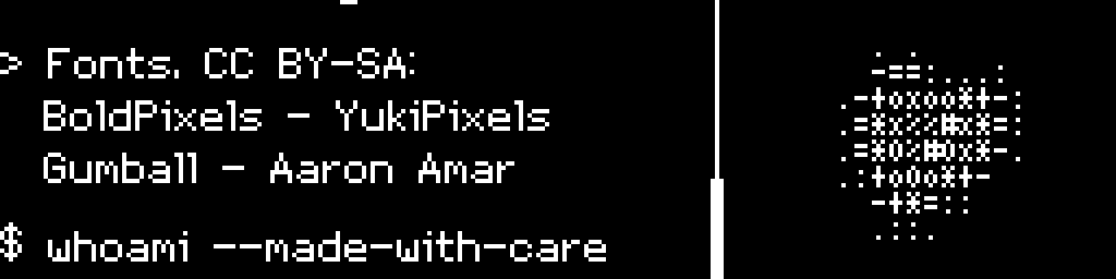
The firmware source and the documentation are published under Apache 2.0, at github.com/Endothermal-Systems/CinderClock. The PCB design files, the enclosure models, and the bill of materials publish at launch, once the board has taken its final revision. Two bundled pixel fonts stay under Creative Commons Attribution-ShareAlike with their attributions intact, and their intermediate BDF files ship as well.
Attributions are in the About section.
Firmware releases are written up as they ship.
all dev logs →A running build log is kept on Hackaday.io, and the campaign is on Kickstarter.
The parts
Every active component, as covered above:
| Component | Part | Notes |
|---|---|---|
| Processor | ESP32-S3, N16R8 (16 MB flash / 8 MB PSRAM) | Dev board on pin headers, socketed rather than soldered |
| Display | 3.12" 256 by 64 monochrome OLED, SSD1322 driver | SPI |
| Real-time clock | DS3231 module | I2C, coin-cell backed, modified to accept a non-rechargeable cell |
| Audio amplifier | MAX98357A | I2S Class-D, drives the speaker |
| Speaker | 30 by 30 mm, 4 ohm | About 3 dollars, no official part name |
| Storage | microSD, Adafruit 4682 | SPI, push to eject |
| Environmental sensor | BME280 | I2C, temperature, humidity, and pressure |
| Light sensor | BH1750 | I2C, drives auto-brightness |
| Primary input | Analog joystick with click | Three pins, four directions plus a press |
| Buttons | Four tactile buttons (A, B, C, D) | On a separate riser board; tactile or hot-swap mechanical variants |
| Dismiss button | 100 mm illuminated arcade dome button | Wired to the Action button |
| Battery | Four 18650 Li-ion cells | Tool-free holders, no welding |
| Charge and protection | Dedicated protection board | Over-current, over-voltage, over-temperature, and short-circuit protection |
| Enclosure | PLA, PETG fallback | Two-part 3D printed shell, sliding dovetail joint, 140 by 160 by 170 mm |
Quantities and exact part numbers publish with the bill of materials at launch.

Conclusion
Our goal of making a multi-purpose standalone desktop clock was achieved. Intentions we started with were satisfied.
The key feature of this device is not in any of its functions. The key is how far it can be expanded beyond what it is today, because of the forward looking approach taken at every decision above.
Everything we can open about this project is open. We invite the community to develop it further, to meet the needs of as many people as possible.
This is how we work at Endothermal Systems.
Common questions
Does CinderClock need an app or an account? No. Every feature runs on the device, and there is no companion app, no account, and no service behind it. It can reach the internet for exactly one thing, an update you ask it to fetch, and it works fully without ever doing so.
It has WiFi. Is it really offline? Yes, in the sense that matters: the WiFi is off at boot, it is started deliberately, it serves only to open a file transfer portal and to install firmware. The decision to turn it on is fully yours.
What exactly is open source? The firmware source and the documentation, under Apache 2.0, published now on GitHub. The PCB design files, the enclosure models, and the bill of materials publish at launch, so the parts list can be checked against the price. Two bundled fonts remain under CC BY-SA with attribution.
How long does the battery last? We do not know yet. The device is designed around a 2 week target, optimizations and testing are underway.
Why does it cost more than a marketplace alarm clock? It is a different class of object. A marketplace clock is a screen with a small computer behind it and a fixed feature set. CinderClock is a programmable device with a published parts list, replaceable modules, and open design files, built to last and easily repaired.
Can the hardware be modified? Yes. Every active component is a breakout module on pin headers, the main PCB is through hole, and the control riser is a separate boardd. The live buses are broken out on labelled headers, including the audio bus, so even the amplifier can be swapped without a board revision.
START A PROJECT →
CinderClock launches soon. Subscribe to be among the first ones to know.
Backers on the list get the launch price.
This list is only for CinderClock.
P.S. It is called CinderClock because a large white boxy shape looks like a cinder block.
Cinder block. CinderClock. Get it?
Related reading: idea to product · hardware prototype cost · pricing and guarantees.